
Connecticut Screen Works Screen Wall System®
Do It Yourself (DIY) - Assembly Instructions
Home manufacture is not an impossible task. DIY'ers of average skill will be able to assemble simple 4-sided Master Frame panels,when utilizing proper tools and work environment, with little trouble.


Our recommended tool list and assembly procedure should accommodate most projects. You may use any equipment, tool or process that you feel will work better or best fits your skill level. Assembly jig detailed is recommended for ease of assembly, but not required.
Tools Required:
- 1) A Miter Saw suitable for cutting metals and properly equipped with a blade approved for aluminum cutting
- 2) Power Drill
- 3) #26 Drill Bit(s)
- 4) Power Screw Gun
- 5) P2R Philips sheet rock driver bit
- 6) A work table or area that is at least as large as the largest panel to be assembled / screened
- 7) Assembly jig
PLEASE READ ALL STEPS LISTED PRIOR TO STARTING
The following recommended instructions assume that you have properly planned your sizes and have received all required components. (Master Frame extrusions, Corner Inserts, Assembly Screws, Screen Material, Spline, and Divider Extrusions (if needed) and Divider Extrusion installation screws (if needed).
WORK 1 FRAME AT A TIME
Before you even make the first cut, pre-plan your cuts. Make a cut list so you are able to achieve the best results from your materials. You should make all of the same size cuts at the same time. Cutting and assembly will require approximately 3/4 to 1 hour per screen frame.

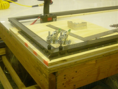
Assembly Jig: A very simple jig is recommended to help hold frame sections in place while drilling and screwing. A fancy industrial machine is not required. Our shop guys put together this example using materials available at almost any hardware store or lumber yard. All that is required is that your jig must hold your corner secure, square, and level.

Cut (MITER CUT) Master Frame Extrusions to the proper length. Remember you'll need 2 for each height and 2 for each width. Use a cutting jig, (material stop) if possible, to ensure all pairs are cut to the exact same size. There is very little play available during assembly so your pairs must match. Note: When cutting, the spline channel must be cut to the inside of the angle.
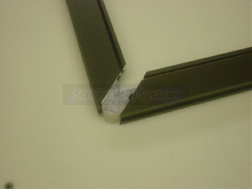
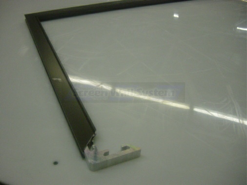
Assembly should be performed 1 corner and 1 frame at a time. (Do not pre-drill or pre-install corner inserts.) Insert a corner insert into 1 end of a width cut. Install a height cut onto the opposite end to form a right angle.
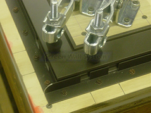
Place corner assembly into a holding jig. Position so corner is clean and tight. As shown, a fancy jig is not required. It simply must hold the frame square, level and tight.
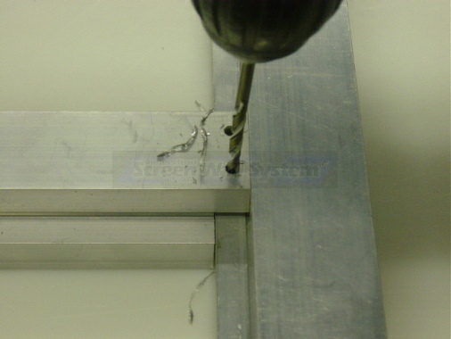
Using a #26 drill bit, drill 1 hole at any of the 4 drilling positions. Drilling positions are centered on the drill line and positioned at 1-1/2" and 3-1/4" from outside edge in on all corners.
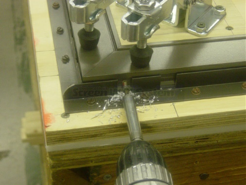
Install 1 assembly screw into the drilled hole.
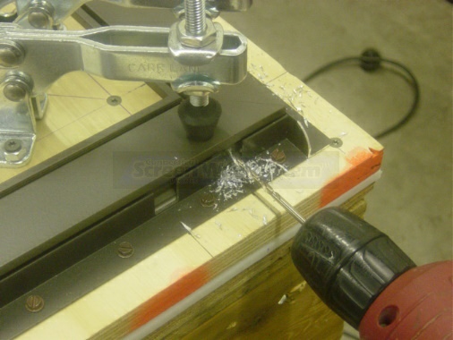
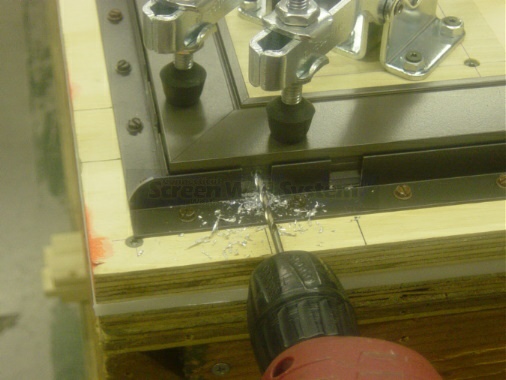
Using a #26 drill bit, drill 1 hole at any of the 2 drilling positions on the opposing side. Watch carefully as you drill - if your jig is loose the frame may "walk" during this operation creating a gap in the corner. If required, hold frame tight to ensure no movement occurs. (most assembly mistakes will happen at this step)

Install 1 assembly screw in the drilled hole.
Using a #26 drill bit, drill the remaining 2 holes and install assembly screws.
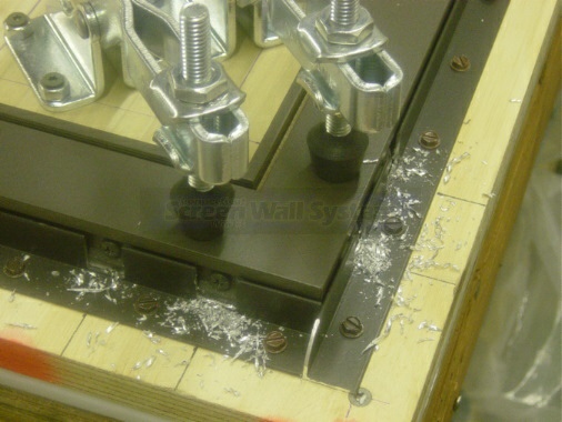
Ensure all 4 assembly screws are secure.

Remove the assembled corner from your jig and blow out all debris.
Place corner insert into shortest leg of your assembly.
Install the next leg of your frame onto the corner insert.
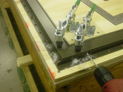
Secure this corner into your jig and follow the exact same drilling and screwing procedure used with the first corner.

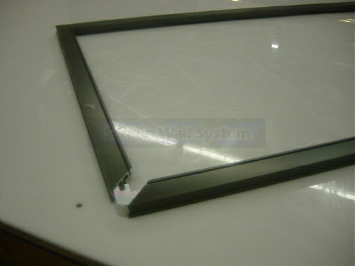
After two corners are assembled, insert the remaining two corner inserts into both ends of the final extrusion cut. Pre-assemble the frame by installing the corner inserts into the 3 sided frame already assembled.
Drill and screw assemble the remaining two corners following the exact same drilling and screwing procedure from above. Repeat the assembly process for each frame required.
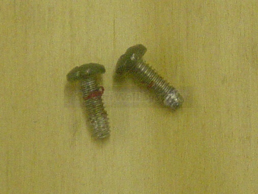
Always ensure that your drill holes are clean of debris. If your screw(s) begins to bind at anytime during installation, stop, remove and discard the screw. Assembly screws can become bound with drilling debris (see photo) making them un-installable. Replace the screw with a new one. NEVER attempt to force the screw into position or reuse a bound screw.
What to do if corner gaps occur during the assembly process. You may be able to correct the problem by placing the problem corner back into your assembly jig and follow the process listed: (this will make the Master Frame screw hole larger allowing for adjustment)
- 1) Make sure frame is tight in your jig. (the gap occurred due to movement during drilling or a poor alignment to begin with)
- 2) Remove the 2 screws from one side of the corner.
- 3) Using a 3/16" drill make the screws holes larger in the Master Frame Extrusion only. DO NOT DRILL INTO THE CORNER EXTRUSION.
- 4) Replace the removed screws but do not fully tighten.
- 5) Loosen the clamp holding this corner side only and attempt to reposition the Master Frame. The larger holes in the Master Frame will allow for slight repositioning.
- 6) You may also need to perform this routine for the opposite corner side.
Connecticut Screen Works Screen Wall System®Divider Extrusion
Our recommended tool list and assembly procedure should accommodate most people. You may use any equipment, tool or process that you feel will work better or best fits your skill level. Assembly jig detailed is recommended for ease of assembly, but not required.
Tools Required:
- 1) Table Saw suitable for cutting metals and properly equipped with a blade approved for aluminum cutting.
- 2) Painters Tape
- 3) #27 Drill Bit(s)
- 4) Counter Sink Bit (Deburing Bit)
PLEASE READ ALL STEPS LISTED PRIOR TO STARTING.

As with the Master Frame process, pre-plan your cuts. Make a cut list so you are able to achieve the best results from your materials. Cutting and assembly will require approximately 1/2 to 3/4 hour per divider. The following recommended instructions assume that you have already assembled your Master Frame panels and have not yet cut the Divider Extrusion(s)

Measure for proper length at the mounting location. This is the clear distance from shoulder to shoulder. Cut the Divider Extrusion to the exact size measured. Cover exposed face of Divider Extrusion with painters tape prior to notching. This will help prevent scratching during notching. (note: photo details notch already cut into extrusion)


Remove a 1/2" x 1/2" (notch) from each end of your cut. Material is removed from the spline side of the extrusion. This may be done with a properly outfitted table saw, milling machine, hack saw, etc. (use of table saw shown above)
Test fit your cut. Provided your cut is clean and square, the Divider Extrusion will fit snug and clean. If you need to reduce the length for fit, remove only a slight amount at a time from one end only. Cut the full length and re-notch. Repeat as needed to produce a snug fit.


You may use a jig to drill divider mounting holes as detailed -or- free drill the mounting holes We recommend the use of a simple drilling jig to ensure all holes are placed in a uniform position on all dividers. This jig, as shown, utilizes a section of divider extrusion which helps to ensure your notch is correctly cut. Drill two holes at each end of the Divider Extrusion using the #27 drill bit. Holes are positioned 3/16" in from cut end and 5/16" inward from the top and bottom. As with the jig shown in the prior set of instructions - jigs need not be fancy.
Place Divider Extrusion into your frame at the exact location for mounting. Using the holes that you have already drilled as guides, drill into the Master Frame
penetrating the first layer of aluminum and then just slightly into the backside of the spline channel. Drill no deeper than 11/16" or you will drill through and into the spline channel. (don't fret if this occurs - simply run your spline over the holes during screen material installation)

Counter sink all drill holes.

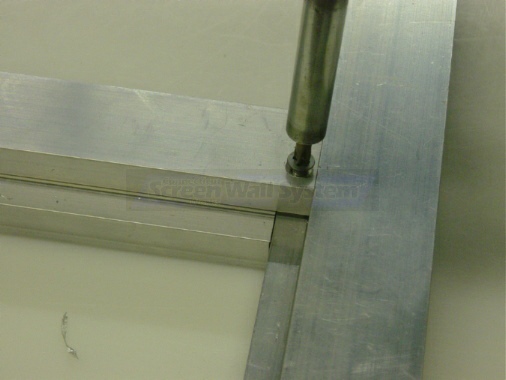

Secure both ends of the Divider Extrusion with two Divider Installation Screws per side. Screws should be set snug.


Completed installation shown from both sides.
Repeat procedure for each Divider Extrusion to be installed. This procedure is the same for all installations: Divider Extrusion to Master Frame and Divider Extrusion to Divider Extrusion.